The aim of my first project here is :
- To experiment with 3D printing
- To experiment with small driveunits/chassis for N finescale
Starting point is a N scale kit from Möllehems Gaardsproduktion in Sweden
www.mollehem.se
The prototype design was made by Hilding Carlson in Sweden. I Norway we had three at NSB and one at the private Askim-
Solbergfossbanen. The NSB railbuses was typically painted redbrown with a yellow stripe. The Solbergfoss railbus was painted silver. Today this one is preserved by NJK (the norwegian railway preservation group)
http://www.njk.no/

The kit has a quite nice plastic superstructure. The chassis is also cast in plastic with a Mashima motor and NEM wheels. I have not tested the chassis / drive because I wanted to try out some ideas about making a chassis in 3D printed metal and I wanted the finescale wheel standard. I also wanted to see how a 6mm dia motor behaved in this model and I wanted free see through windows. On top of that I wanted DCC + sound +light
So far I have designed a new splitframe chassis / drive and got it printed in brass from Imaterialise
https://i.materialise.com/ . From Shapeways
http://www.shapeways.com/ I have got printed in FXD (Frosted Extreme Detail) a two part pivot for one axle. Only the rigid axle will be driven. In POM I have turned muffs for the split axles and pins to connect the two chassis halves. So far this have worked out well.
 |
| 3D file |
Here is a picture of my .STL file for 3D print. It is massive for weight and split for good pickup of the current via the wheel axles. There is a circular room in the middle for the 6mm motor. Diameter is 6.4mm to make room for isolating the motor from the chassis. The small circular opening is for mounting a compensating device for the non driven axle.
This have now been adjusted to a rectangular hole by filing.
 |
| The kit includes etched part |
In the next picture I have included the two part
plastic chassis and the etched parts included in the kit.
 |
| The 3D printed halves |
This picture shows the two parts of the 3D printed chassis with all the nessessary cavities for the motor and the drive components. The rigid drive axle to the left and opening for the pivoted axle
 |
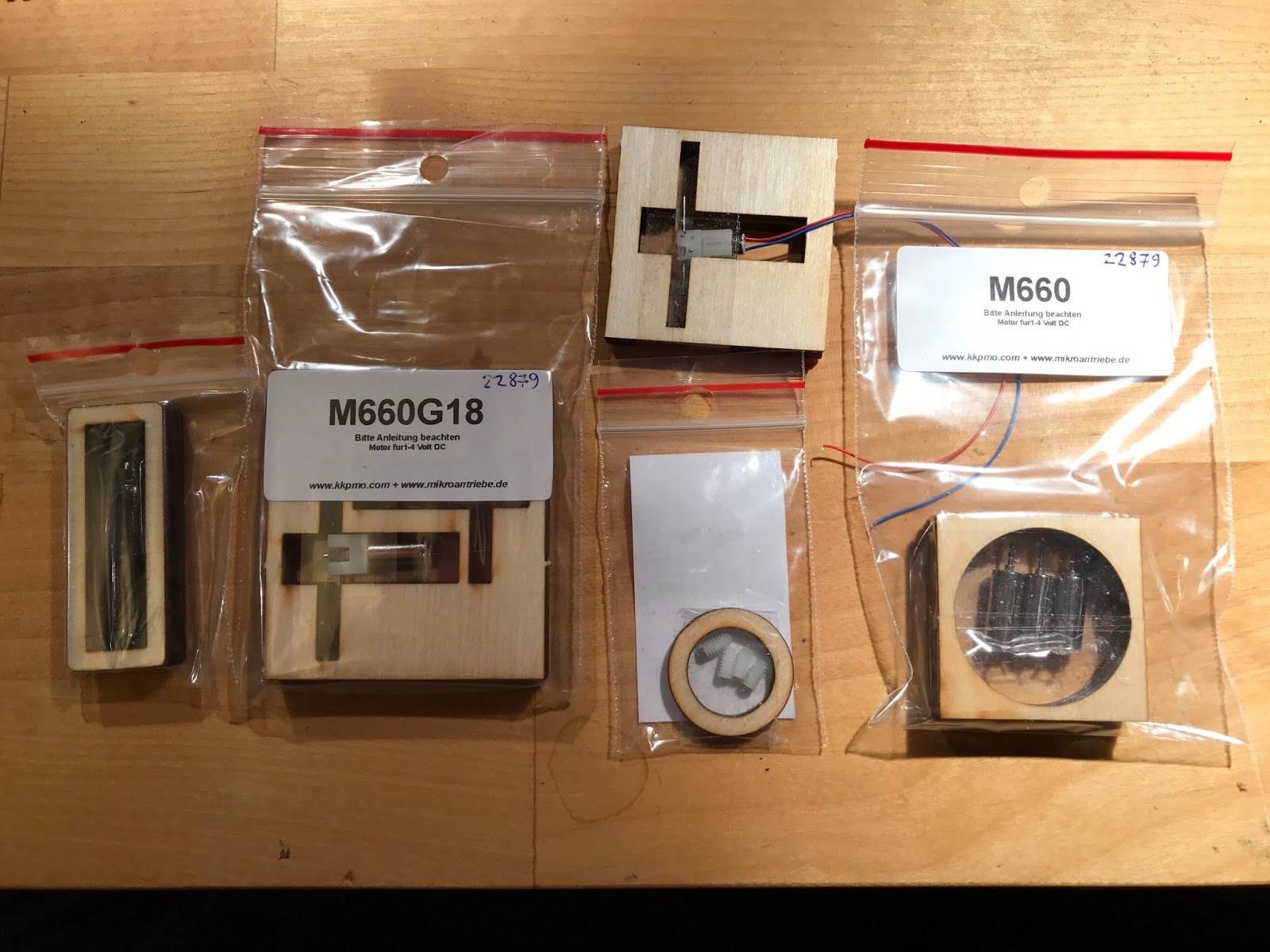
| All the parts I have so far. |
On top is the loudspeaker from CT elektronik
http://www.tran.at/ then the FS wheels turned in steel on my old unimat3 lathe. The 1mm dia axle is not separate, but turned integral with the wheel. It gives a wobblefree wheel. Between the frames is a 6x12mm motor from Mikroantriebe with worm (1:18) The white bands are turned from POM plast on my lathe, 0.2mm thick. The decoder is from CT but will be replaced by a CT sounddecoder. Under the frames : The two taps to assembe the frames are turned POM and the two part pivot for one axle 3D printed from FXD
 |
| Seen assembled from the underside |
The wheels preliminary mounted with muffs turned from POM and the gearwheel pressfitted on.
 |
| Seen assembled from the side |
 |
| Seen assembled from above |
 |
| with the superstructure added shows the see through effect |